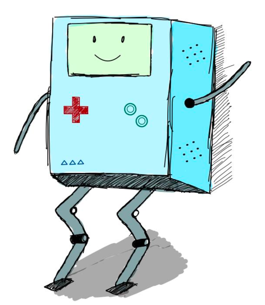
BMO is a legged robot developed in a hands-on robotics studio course, where the challenge was to take a project from concept to functional prototype. The robot was designed to walk using serial bus revolute servomotors, with all subsystems, from kinematics and structure to electronics and control, built and integrated from the ground up.
My Role
Co-led the design and construction of a two-legged walking robot with eight DOF. Developed kinematics, CAD modeling, structural shell, and motion programming; integrated hardware and software subsystems into a working prototype.
The Design Prompt
• Design and build a functional legged robot using no more than eight serial bus servomotors.
• Robot must achieve a stable walking motion.
• Integrate mechanical, electrical, and programming subsystems in a compact, manufacturable design.
Goal: Build a walking robot that combines technical rigor in mechatronics with a thoughtful, cohesive design.
Design Process
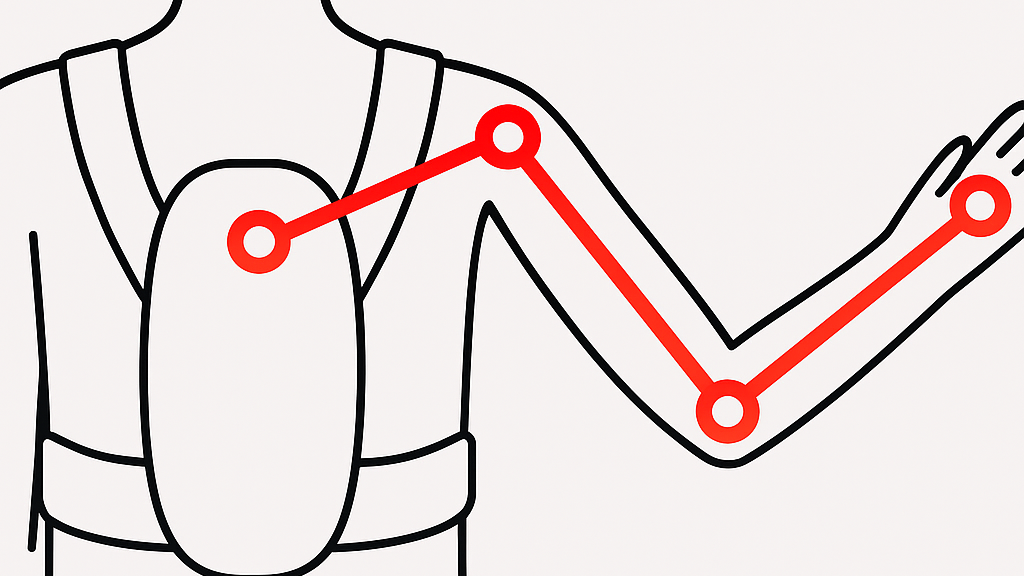
Kinematics & Structure
The foundation of the design was a bipedal system with eight degrees of freedom, four revolute joints per leg, which provided enough mobility for forward walking and basic balance. The gait cycle was refined through a combination of inverse kinematics modeling, CAD simulation, and hands-on prototyping, adjusting servo torque limits and timing to smooth out motion. The chassis and leg structures were modeled in SolidWorks with a focus on weight distribution and manufacturability, and 3D-printed parts allowed us to quickly iterate on geometry while maintaining structural strength. These refinements helped the robot shift from stumbling steps to repeatable forward motion.
Electronics & Control
The electronic subsystem centered on serial bus servomotors controlled by a single-board computer, with feedback provided by an IMU and accelerometer. We programmed motion sequences using closed-loop control, fine-tuning servo positions and gait timing until the robot could reliably complete multiple walking cycles. Through trial and error, we discovered how small changes in timing dramatically influenced stability, so iterative testing was critical. Battery efficiency also played a major role — early tests drained power too quickly, so we optimized motion sequences to conserve energy without sacrificing performance.
Human-Centered Design
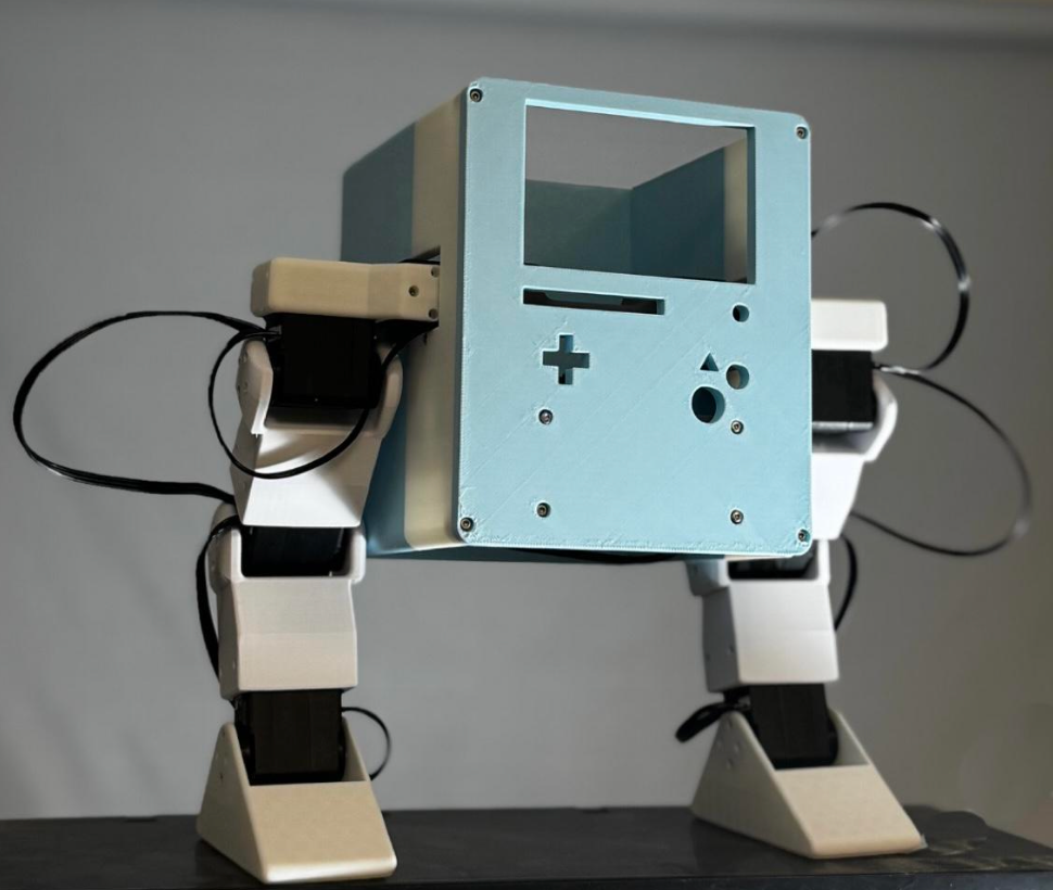
While engineering drove the project, I also wanted the robot to be approachable, which led to designing a lightweight shell inspired by BMO from Adventure Time. The shell balanced playfulness with functionality: it gave the robot a distinct identity while protecting internal wiring and leaving key areas accessible for iteration and repair. Designing for modularity was key. The shell could be removed or adjusted easily, making the robot both user-friendly for testing and expressive in form.
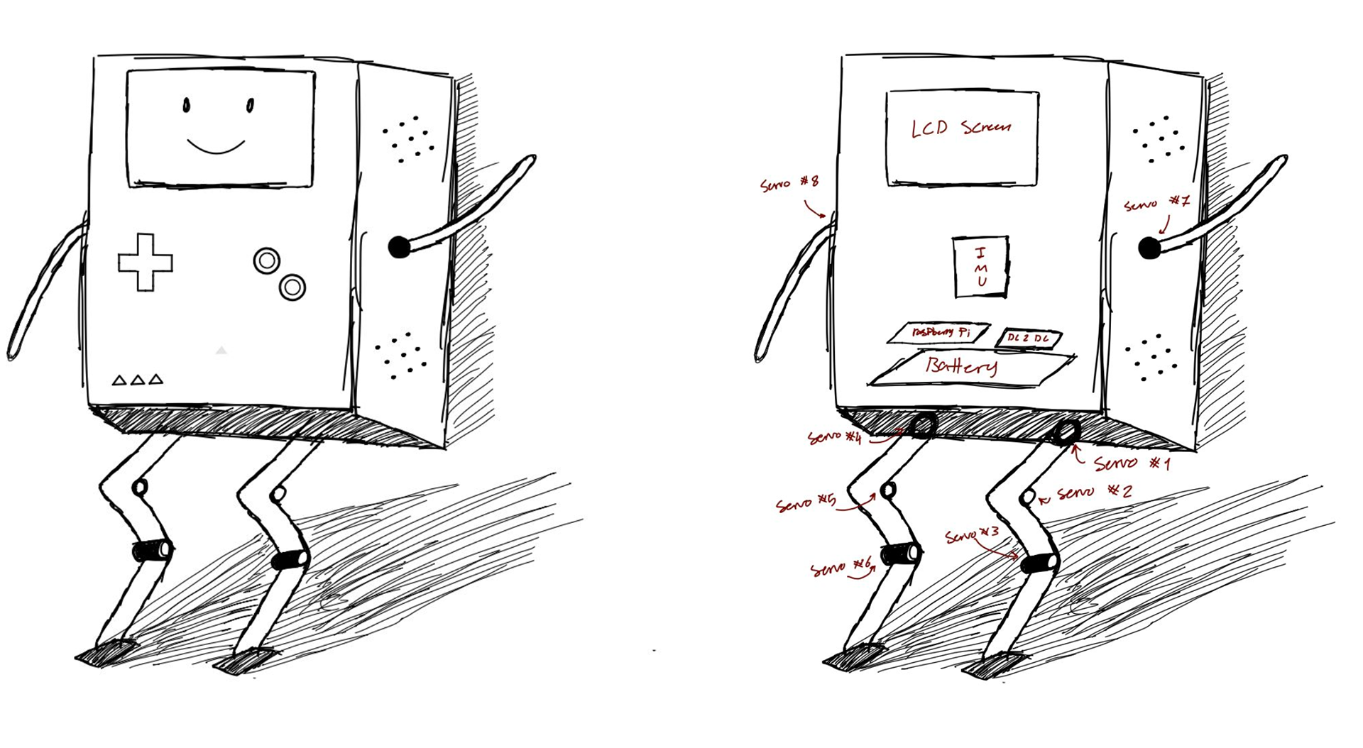
Sketches and electronics planning
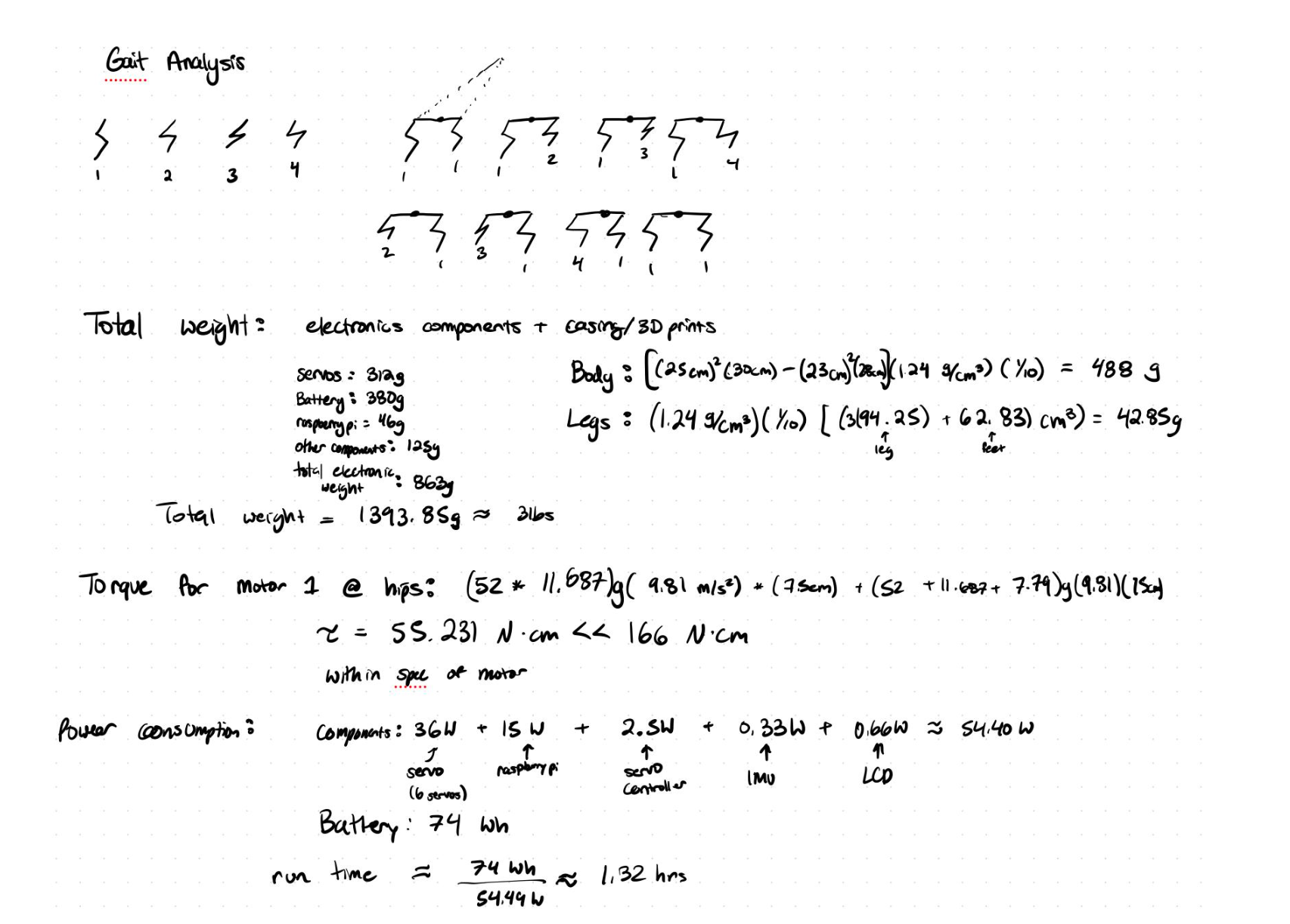
Early calculations
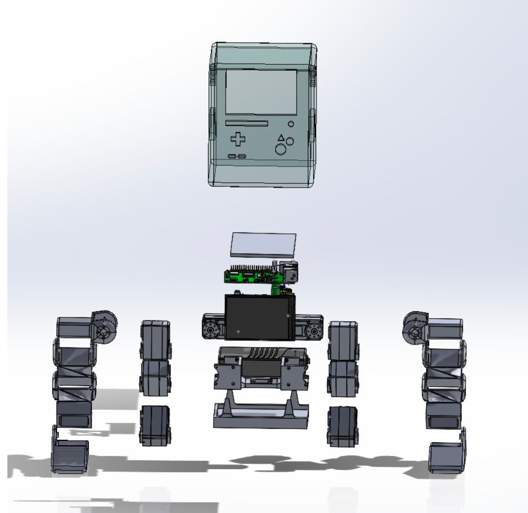
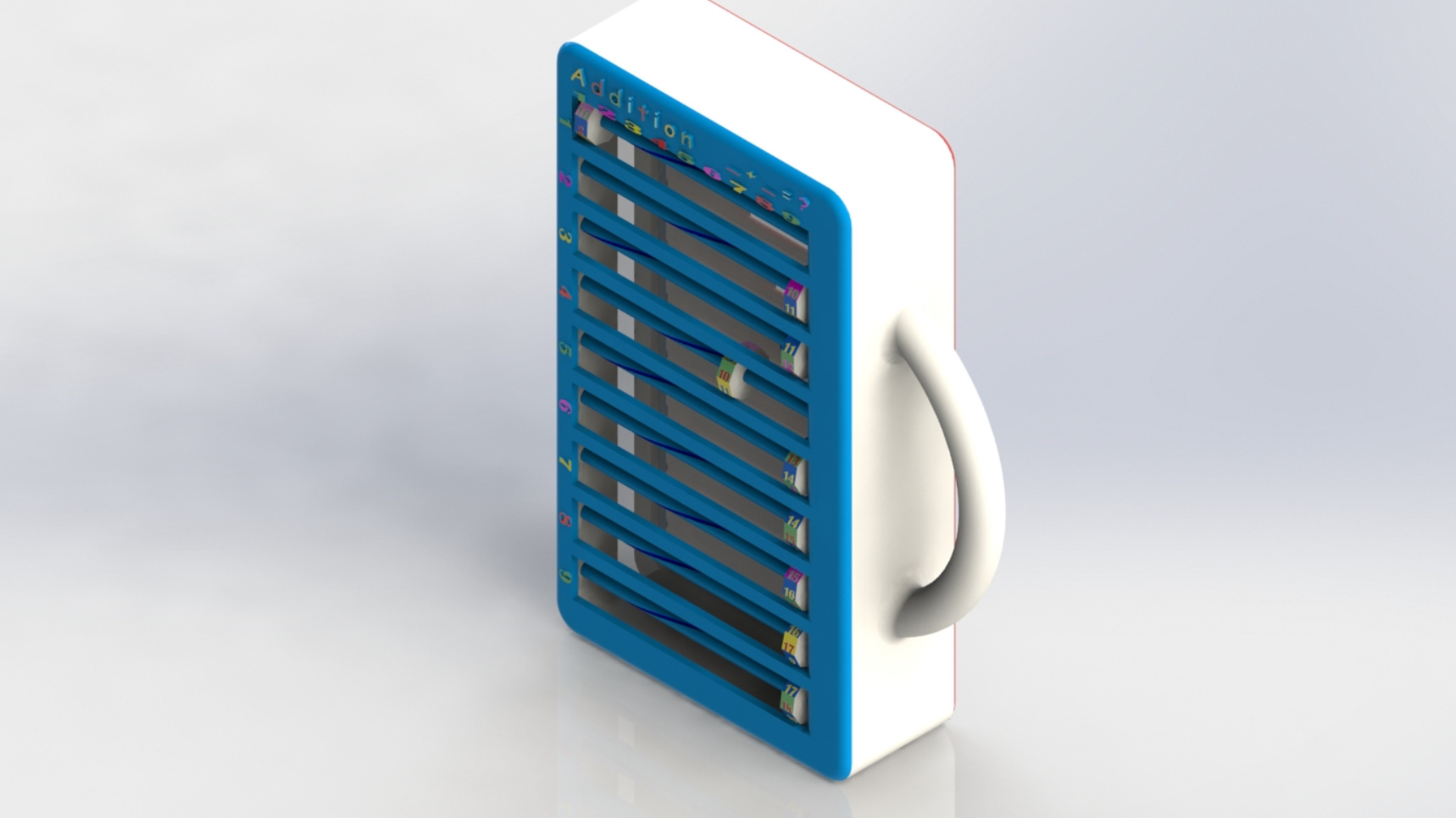
Exploded view of CAD

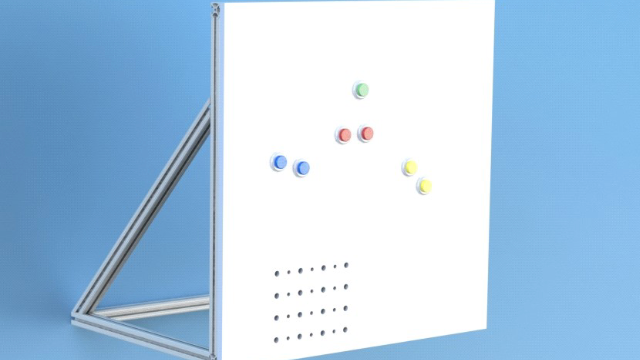
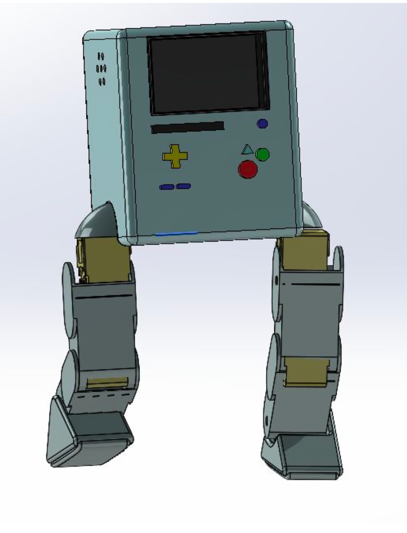
Final component layout
Challenges
Early prototypes struggled with balance, often toppling after one or two steps, which led us to lower the centre of mass and refine gait timing and torque limits until the walking cycle stabilized. Power consumption also became a challenge, with the battery draining quickly during prolonged trials, so we optimized the gait to reduce unnecessary joint activation. Finally, the aesthetic design of the shell had to balance user appeal with structural efficiency, which required several iterations before arriving at a design that worked for both function and form.
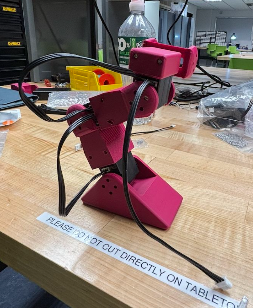
Testing 2nd leg prototype
Before lowering COM
Results & Reflection
• BMO achieved 25+ cm/s stable walking spee
BMO demonstrated how robotics projects demand both engineering rigor and thoughtful design. By uniting kinematics, controls, electronics, and manufacturability with a playful aesthetic, the project highlighted the importance of building systems that are not only functional but also engaging, approachable, and designed for iteration.